Venting Some Pressure (ProMax Depressurization Tool)
Craig Spears
November 17, 2015
The ProMax Depressurization Tool is available to calculate the temperature, pressure, and mass flow rate profile for a vessel that is venting,
including heat input cases, such as an external fire. It is designed to assist you with several related scenarios, and to provide you with
information on the venting and non-vented material compositions.
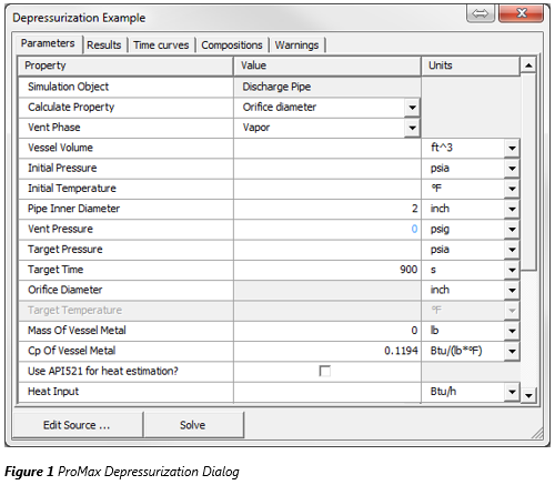
1. Choose the object to Depressurize
Streams, Separators, Pipelines, and Columns are valid selections on which to base the depressurization calculations.
2. Choose the calculation you need
The ProMax Depressurization tool can perform several different calculations depending on the scenario you would like to investigate.
CASE 1: Orifice Diameter
Calculates the Orifice Diameter required to depressurize the system from an Initial Pressure to a Target Pressure in a specified amount of time (Target Time) with or without heating.
CASE 2: Time to Reach Target Pressure
Calculates the time required (Target Time) to depressurize the system from an Initial Pressure to a Target Pressure for a specified Orifice Diameter with or without heating.
CASE 3: Pressure after Set time
Calculates Target Pressure down from an initial Pressure in a specified amount of time (Target Time) for a specified Orifice Diameter with or without heating.
CASE 4: Pressure relief with time limit
This calculates the valve size required to maintain a specific relief pressure over a specified period of time in a Fire Case. The material that needs to be
removed at any interval to maintain the relief pressure is used with the relief valve sizing equations to size the required valve. The Heat Input must be supplied or estimated by API 521.
CASE 5: Pressure relief with temperature limit
This calculates the valve size required to maintain a specific relief pressure without exceeding a specified temperature in a Fire Case. The material that needs to be removed at any interval to
maintain the relief pressure is used with the relief valve sizing equations to size the required valve. The Heat Input must be supplied or estimated by API 521.
Note: The VBScript embedded in the stencil employs methods described in Crane Technical Paper 410 (2009). This script may be tailored if desired by selecting the “Edit Source...”
button at the bottom of the dialog.
3. Set the Venting Phase
ProMax supports only single phase discharge for the Depressurization calculations: vapor, light liquid, heavy liquid, or mixed liquid. If the relieving pressure exceeds the critical pressure of
the components in the system, it is best to use equation of state correlations capable of estimating pressure, temperature and enthalpy relations in the critical regions.
4. Specify the Vessel Volume
ProMax will estimate the vessel volume when possible. In the case of a sized separator, the calculated vessel internal volume is used. For a column, the total volume is calculated by adding
each stage volume using the diameter, tray spacing or packing height, and number of stages, plus additional volume above the top stage and below the bottom stage. For a pipeline, the internal
diameter and length information is utilized, in addition to reducer volumes (other fittings are assumed to occupy negligible volume). For any case, the volume may be supplied or overwritten
with a more accurate value.
5. Set the Depressurization Conditions
Initial Temperature and Pressure – These are the conditions at which the venting begins. If unspecified, ProMax will use the following:
Streams:The temperature and pressure of the stream.
Pipes:The temperature and pressure of the Pipeline block outlet stream.
Separators:The temperature and pressure of the Separator inlet stream
Columns:The pressure of the top stage, and the temperature is the adiabatic mixing of all internal (stage) PStreams at the lowest stage pressure of the Column.
Pipe Inner Diameter This is the venting pipe diameter. Typically, vent systems have an outlet pipe followed by a pressure relief valve or discharge orifice.
Vent Pressure This is the downstream pressure where the vented material goes, similar to the backpressure concept in relief valve sizing.
Target Pressure This is the desired pressure after venting, and is a required specification for all cases except “Pressure after set time”. It must always be
greater than the vent pressure, as a pressure lower than the back pressure cannot be achieved. For non-“Pressure Relief” cases, it must be lower than the initial pressure.
For “Pressure Relief” cases, it must be greater than the initial pressure.
Target Time This is the time required to reach the Target Pressure from the initial conditions, and is a required input for the “Orifice Diameter”, “Pressure after set time”,
and “Pressure relief with time limit” scenarios.
Orifice Diameter This is the vent opening or relief orifice diameter. If the orifice is considered to be a nozzle, then it is the nozzle throat diameter. ProMax will
calculate this for the “Orifice Diameter” case. For “Time to reach target pressure” and “Pressure after set time” cases, it must be specified. For both “Pressure relief” options,
this remains blank and relief information can be found in the Results tab instead.
Target Temperature This is the temperature limit specified for the “Pressure relief with temperature limit” case. In all other cases, this is the calculated
temperature for the system once it reaches the target pressure.
6. Estimate Heat Input
Heat input can be due to any emergency scenario, such as a cooling jacket failure, runaway reaction, fire, etc… ProMax allows for the heat input to the system to be either directly specified or to
be estimated by the API 521 methodology. If your case has no heat input, a value of zero can be set. Recent calculations indicate that the heat flux of the fire is in the range of approximately
25,200 Btu/ft2·h to 31,500 Btu/ft2·h, although this depends on several variables.
If you choose the API 521 estimation for an external flame, several additional specifications are required to help calculate a reasonable approximation. The heat input from this method is
time-dependent because it is a function of a wetted surface area, which decreases as depressurization and venting occurs. This is more realistic than a static heat value, but generally does
not significantly affect the sizing of the orifice.
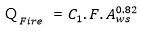
API 521 recommends using the following equation for estimating the Heat Input, where Q is the total heat absorption to the wetted surface in watts (W):
Constant Value (C1)
C1 = 70,900 for cases without adequate drainage or firefighting equipment. If firefighting is available, use the alternative constant C2 = 43,200 instead. ProMax chooses this value based on your “Firefighting Available” selection.
Environment Factor (F)
F is the environment factor as shown in API 521, and the value depends on whether the vessel is insulated or not, the insulation conductance
values if insulated, the presence of water-application facilities, and if the vessel is earth-covered or below grade. In the Depressurization Tool,
the “Tank Surroundings” option determines this value (if “Insulated” is selected, the “Thermal Conductivity” must be supplied as well.)
Wetted area (AWS)
This is the area covered by liquid inside the tank (in m2).
The major contributor to over pressure in fire cases is the vaporization of the liquid in the vessel due to the heat input. The portion of surface area that contains liquid in a vessel is called the “wetted surface” of a vessel,
and this is the only portion considered when determining the rate of vapor generation. Further, experience has shown that it is only necessary to size relief devices for the wetted surfaces within 25 feet above the source of the flame. Various
classes of vessels are operated partially full, and there are different recommended portions of liquid inventory for use in calculations.
ProMax will calculate this value for cylindrical and spherical tank shapes based on the volume of the vessel and the volumetric liquid fraction. For this calculation, the volume of the liquid in the vessel should be known, and a few more pieces of information should be supplied.
- Tank shape – This refers to the shape of the tank being depressurized, “Horizontal Cylinder”, “Vertical Cylinder”, “Spherical”, and “Irregular”.
- Tank length to radius ratio – This is used for calculating the surface area for the tank. It is only relevant for cylinder tank shapes, and will be unavailable for other shapes.
- The wetted area for an irregular shape must be user input.
- Tank elevation above grade – this represents the elevation of the tank bottom from ground level. Wetted surfaces higher than 25 feet in elevation are excluded from the calculation.
- Un-wetted area factor – total vessel area minus the wetted area
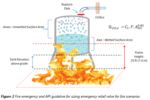
7. Review the Results
Once you have specified and solved the Depressurization case, the Results Tab will present the calculated Target Pressure,
Target Time, Orifice Diameter, or Maximum Orifice Area and flow conditions depending on the scenario you ran. The Time curves and
Compositions tabs will contain additional information about the depressurization for you, as well. Any of the results ProMax generates
can easily be transferred to Excel for additional analysis or plotting.
Note: If you are using the Depressurization Tool on an electrolytic flowsheet, the results may take an extended time to calculate. Selecting the “Use EOS for liquid phase” option will increase the calculation speed, but at times may predict a third phase
resulting in an error when the Electrolytic Package predicts only two phases. This option is not recommended unless necessary.
REFERENCES
American Petroleum Institute (2007). “Pressure Relieving and Depressurizing Systems” API 521, 5th Edition.
Fisher, H.G. (1995). Protection of Storage Tanks from Two-Phase Flow Due to Fire Exposure, Process Safety Progress, Vol.14, No.23
Huff, J.E (1982). Emergency Venting Requirements, Plant/Operations Progress, Vol.1, No.4
Leung, J.C. (1986). Simplified Vent Sizing Equations for Emergency Relief Requirements in Reactors and Storage Vessels, AICHE Journal, Vol.32, No.10
Leung, J.C. (1987). Overpressure During Emergency Relief Venting in Bubbly and Churn Turbulent Flow, AICHE Journal, Vol.33, No.6
Salater, P., Overaa, S.J., and Kjensjord, E (2002) Size Depressurization and Relief Devices for Pressurized Segments Exposed to Fire, CEP