Pressure Relief Valve Sizing
Craig Spears
November 10, 2015
Pressure relief valves are used to protect equipment from excessive overpressure. Properly sized relief valves will provide the required protection, while also avoiding issues with excessive flow rates, including: possible valve damage, impaired performance, undersized discharge piping and effluent handling systems, and higher costs.
Many scenarios can result in an increased vessel pressure, and each scenario may result in a different valve size. It is generally recommended to perform multiple case studies to find the most conservative sizing. Some typical cases include:
- a run-away reaction,
- a loss of cooling,
- thermal expansion of a liquid, or
- an external fire.
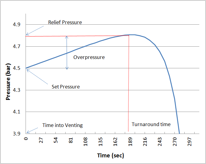
In any of these scenarios, the pressure will increase until a predetermined relief pressure is reached, at which point the relief pressure valve will open, decreasing the pressure after the turnaround time. The first step in sizing a Relief Valve in ProMax is to determine which scenario you are interested in modeling.
The Relief Valve Sizing in ProMax is performed as a stream analysis. Any stream in ProMax may have one or more Relief Valve Sizing Analyses added, so multiple cases can be studied in a single stream if desired.
1. Choose the Relief Valve Standard
There are many different standards for Relief Valve Sizing, each applying different assumptions, thus giving different results. For instance, API 520, one of the most cited standards, assumes both a mechanical and thermodynamic equilibrium, and constant phase properties during relief. Alternatively, the EN ISA 4126 standard accounts for thermodynamic non-equilibrium. ProMax currently supports six different sets of Relief Valve Sizing Standards:
- ASME API RP520 (7th edition, January 2000) – USA
- EN ISO 4126 – Europe
- AD Merkblatt A2 – Germany
- DIN 3320 – Germany
- TRD 421 – Germany
- BS 6759 - United Kingdom
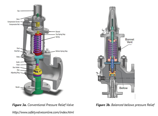
2. Select the Appropriate Valve Type
Next, an appropriate relief type must be selected, as sizing depends on the type of relief device selected. The operation of conventional spring-loaded pressure relief valve is based on a force balance: the spring-load is preset to apply a force opposite in amount to the pressure force exerted by the fluid on the other side when it is at the set pressure. When the fluid pressure exceeds the set pressure, the pressure force overcomes the spring force, and the valve opens. Any back pressure (downstream pressure) is additive to the spring force; if this back pressure varies, then the pressure at which the valve opens will vary. Bellows are used to maintain a constant relief pressure despite back pressure variations. Rupture disc relief valves do not reclose after activation; preference should usually be given to reclosing relief devices for both safety and reliability. The most common valve types include:
- Conventional- spring loaded pressure relief valve whose operational characteristics are directly affected by changes in the back pressure.
- Conventional + Rupture Disk - Conventional valve with a rupture disk.
- Balanced Bellows - spring loaded pressure relief valve that incorporates a bellows for minimizing the effect of back pressure on the operational characteristics of the valve.
- Balanced Bellows + Rupture Disk - Balanced Bellows valve with a rupture disk.
- Pilot Operated - a pressure relief valve in which the major relieving device or main valve is combined with and controlled by a self-actuated auxiliary pressure relief valve (pilot).
- Pilot Operated + Rupture Disk - Pilot Operated valve with a rupture disk.
- Rupture Disk Only - a valve with a non-reclosing pressure relief device, actuated by static differential pressure between the inlet and outlet.
3. Set the Relief Temperature
The Relief Temperature is determined by which pressure relief scenario you have chosen to model, and should be the temperature of the fluid at the time that the valve is expected to open. ProMax assumes that the Relief Temperature will be the current stream temperature, however, if your particular scenario requires that this be adjusted, it can be overwritten directly in the analysis dialog.
4. Set the Relief Pressure
The Relief Pressure is generally determined by the equipment being protected, and is calculated as Relief Pressure = Set Pressure + Overpressure. By default, ProMax uses the stream pressure as the Set Pressure, and a 10% Over Pressure, but these can be modified for your analysis.
Set Pressure
A relief device’s maximum allowable Set Pressure is equal to the vessel’s Maximum Allowable Working Pressure (MAWP) for vessels protected by a single relief device. The MAWP is set according to a specific temperature, the Maximum Allowable Working Temperature (MAWT). As the MAWT increases, the MAWP decreases because of the reduction in strength of metal at higher temperatures.
However, relief devices are typically set to open at the design pressure, instead. In some cases, the design pressure is equal to the MAWP – but it will never exceed it. In cases where the MAWP is not well-established, the design pressure may be used for the set pressure.
The Set Pressure is usually given in terms of gauge pressure, therefore any Back Pressure is added to the set pressure and overpressure to calculate the Relief Pressure in absolute units. The Back Pressure includes both the constant superimposed downstream pressure and any built-up backpressure due to the discharge of the fluid from the relief device through the downstream piping and treatment system.
Over Pressure
The Over Pressure is usually expressed as a percentage of the Set Pressure. For spring-operated relief valves, a small amount of leakage occurs at 92-95% of the Set Pressure, and sufficient Over Pressure is necessary to achieve full lift. ASME-certified relief valves are required to reach full-rated capacity at 10% or less overpressure.
Note: A similar term, the Pressure Accumulation, is based on the MAWP instead of the Set Pressure. In cases where the Set Pressure is equal to the MAWP, then the overpressure and pressure accumulation are the same. The allowable accumulation for pressure vessels protected by a single relief device is 110% of the MAWP, except in fire exposure scenarios where 121% is allowed. When multiple relief devices are used for non-fire scenarios, the allowable accumulation is 116%.
5. Determine the Required Mass Flow
The default value for this parameter is the mass flow of the stream in the simulation, but it can be set to the desired value for a specific scenario.
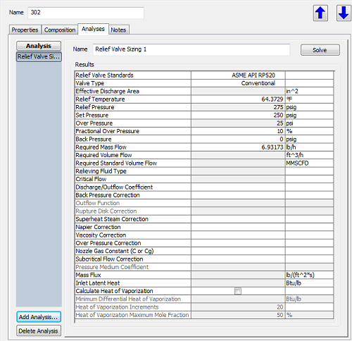
6. Review the Results - the Effective Discharge Area
Once you’ve determined your emergency scenario, and specified the relieving conditions and flowrate, and the appropriate standard, ProMax will calculate the Effective Discharge Area. This value is used to select the appropriately sized Pressure Relief Valve.
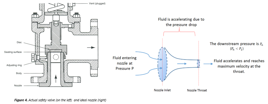
7. How did ProMax Calculate this?
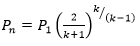
Although an orifice is often used to describe the minimum flow area constricted in the valve, the geometry and relief area calculations are more appropriately modeled based on an ideal (isentropic) nozzle. The expression for the mass flux (Gn) in an ideal nozzle is obtained directly from Bernoulli’s equation in the nozzle:
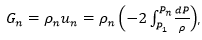 where P1 is the pressure at the valve entrance, P is the fluid pressure, Pn is the downstream pressure, and
 is the density at the nozzle exit.
Mass balance at any point in the nozzle dictates that the mass flow rate is constant:
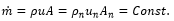 In this equation, un is the fluid velocity at the nozzle throat, An is the throat area, and p, u, and A are the density, velocity, and flow area, respectively,
at any given point in the nozzle. The fluid density decreases as it flows through the nozzle due to the decrease in pressure. Additionally, the flow area decreases as the nozzle restricts, reaching a minimum value of An
at the throat. The velocity u, then must increase, and reaches un at the throat. The rate of increase in velocity is greater than the rate of decrease in density, therefore the mass flux reaches a maximum at the throat.
In this equation, un is the fluid velocity at the nozzle throat, An is the throat area, and p, u, and A are the density, velocity, and flow area, respectively,
at any given point in the nozzle. The fluid density decreases as it flows through the nozzle due to the decrease in pressure. Additionally, the flow area decreases as the nozzle restricts, reaching a minimum value of An
at the throat. The velocity u, then must increase, and reaches un at the throat. The rate of increase in velocity is greater than the rate of decrease in density, therefore the mass flux reaches a maximum at the throat.
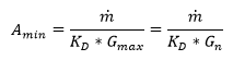
For a given mass flow rate,
 determined for the particular emergency scenario, the minimum required area (Amin) is calculated at the maximum mass flux,
which was determined to occur at the nozzle throat. Real valves are not ideal nozzles, so a discharge coefficient, KD, is
used to account for the difference between the predicted ideal nozzle and the actual mass flux in the valve.
determined for the particular emergency scenario, the minimum required area (Amin) is calculated at the maximum mass flux,
which was determined to occur at the nozzle throat. Real valves are not ideal nozzles, so a discharge coefficient, KD, is
used to account for the difference between the predicted ideal nozzle and the actual mass flux in the valve.
KD (Discharge Coefficient)
The discharge coefficient,KD, can be estimated by ProMax or specified directly from vendor literature.
Gn (Mass Flux)
Single and two-phase flows are both frequently encountered in various relief scenarios. Due to the large number of variables associated with the fluid properties,
distribution of fluid phases, interaction, and transformation of the phases, sizing a two-phase relief scenario is considerably more complex than single-phase. The Mass Flux calculation varies depending on the relieving fluid type:
Single-phase liquid flow
For liquids with constant density, Bernoulli's Equation reduces to 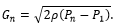 This equation is valid for fully turbulent flow, where the flowrate is independent of the fluid viscosity. For low Reynolds number (high-viscosity) flows, values can be multiplied by a correction factor.
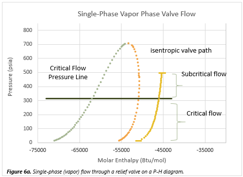
Single-phase vapor
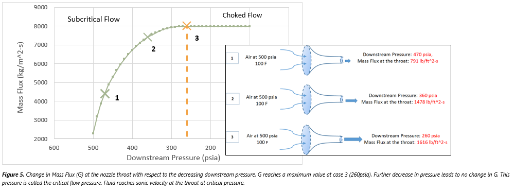
For a vapor flow, the equation used depends on whether the flow rate is critical or subcritical. When the downstream pressure is reduced, the velocity and mass flux increase at the throat; eventually the mass flux
reaches a maximum value at the choked, or critical, flow pressure. Subcritical flow is a function of both upstream and downstream pressures, whereas choked flow is a function of only the inlet conditions.
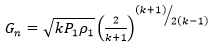
The criterion for choked flow for an ideal gas can be given as
 , where k is the isentropic coefficient (Cp/Cv).
Critical flow:
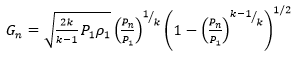
Subcritical flow:
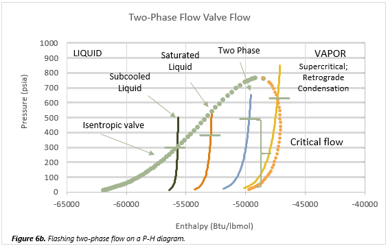
Flashing Two-Phase Flow
The fluid vaporizes along the path of decreasing pressure, and its vapor fraction increases.
Non-Flashing Frozen Two-Phase Flow
Frozen flow occurs if the vessel initially contains both gas and nonvolatile liquid (for instance a vessel with an inert-gas padding), hence it flows at a constant quality
(vapor mass fraction) without significant flashing or condensation.
Flashing Two-Phase Flow with the Effect of Non-Condensable Gases
This type of flow is often encountered at metering devices in chemical processing and in relief valve sizing applications where both non-condensable and condensable (flashing) components
co-exist (e.g., a hydrogenation reaction mixture containing gaseous hydrogen and an organic solution at elevated pressure).
Common Two-Phase Flow Assumptions:
Mechanical Equilibrium -
This assumes that the two phases are flowing at the same velocity, with no slip between the phases. Although there are a variety of models in the literature for estimating the slip as a
function of fluid properties and flow conditions, it is often neglected under pressure-relief conditions because of the high degree of turbulence and mixing.
Thermodynamic Phase Equilibrium -
It is commonly assumed that the gas or vapor phase is in local thermodynamic equilibrium with the liquid phase, meaning the properties of the mixture are a function of only the local
temperature, pressure, and composition. When the pressure drops to the saturation pressure of the liquid, flashing occurs instantly if thermodynamic equilibrium is assumed. However, flashing
is usually not instant and during this period liquid can travel several inches in the nozzle of the valve under typical relief conditions.
Inlet Latent Heat -
This term is an estimation used in sizing pressure relief valves for two-phase liquid/vapor applications when the system has less than 0.1 wt% H2, a nominal boiling range less than 150°F, and
is far from the critical point. It’s important to note that true “Latent Heat” is a pure component property, and extending the definition to a multi-component mixture requires making assumptions.
As such, there are multiple methods of approximating the latent heat, and the Relief Valve Sizing analysis follows the methodology of the standards. For example, the API 520 standard defines “latent heat” as
the difference between the vapor and liquid specific enthalpies at the inlet temperature and bubble point pressure for sub-cooled liquids, and at the inlet temperature and inlet pressure for a two-phase flashing flow.
NOTE: The calculated “Latent Heat” in the analysis should NOT be utilized for Fire-Case Relief Valve
Sizing scenarios. Instead, ProMax provides a Depressurization tool that is useful for these cases.
Calculate Heat of Vaporization -
The Heat of Vaporization calculation is an alternative to the Latent Heat calculation utilizing a batch distillation approach. This calculation generates pseudo instantaneous Heat of Vaporization
values for cumulative amounts of vapor boiled off from the system. Values are generated for the specified number of Heat of Vaporization Increments from 0% up to the specified Heat of Vaporization
Maximum Mole Fraction. The minimum of these values is reported as the Minimum Differential Heat of Vaporization.
REFERENCES
Much thanks to Dr. Ugur Guner for his contributions to this article.
American Petroleum Institute (2000). Sizing, Selection, and Installation of Pressure-Relieving devices in Refineries, API 520 , 7th Edition
Crowl, D., Tipler, A. S. (2013). Sizing Pressure Relief Devices, CEP
Darby, R., Meiller, P. R., Stockton, J. R. (2001). Select the Best Model for Two-Phase Relief Sizing, Chemical Engineering Progress, Vol.97, No.5, pp 56.
Darby, R., Self, F.E., Edwards, V.H. (2002). Properly Size Pressure-Relief Valves for Two-Phase Flow, Engineering Practice
Leung, J.C. (1986). Simplified Vent Sizing Equations for Emergency Relief Requirements in Reactors and Storage Vessels, AICHE Journal, Vol.32, No.10
Leung, J.C. (1990). A Generalized Correlation for Two-Phase Non-flashing Homogeneous Choked Flow, Transactions of ASME, Vol. 112
Leung, J.C., Epstein, M (1991). Flashing Two-Phase Flow Including the Effects of Noncondensible Gases, Journal of Heat Transfer, Vol. 113/269
Schmidt, J., Egan, S. (2009). Case Studies of Sizing Pressure Relief Valve for Two-Phase Flow., Chem. Eng. Technol., Vol. 32, No. 2, 263-272