Keeping Things Cool (Depressurization)
Craig Spears
November 16, 2015
There are many scenarios that can lead to a dangerous increase in the pressure of a vessel: valve failures, utility failures, cooling water problems,
broken fans, electric failures, reflux failures, abnormal heat input from boilers, process control failure on reactors or cryogenic fluids, and many others.
Fundamentally, the cause of increased pressure is due to unexpected mass or heat input.
For this discussion, we will focus on extraneous energy input and the resultant vaporization of liquids and thermal expansion. For this case, the required
relief rates should balance the vapor outflow rate with the maximum rate of vapor generation (if present), vapor thermal expansion due to heat input and
pressure reduction, and liquid flash due to the pressure reduction. Generally, the rate of vapor formation is approximately equal to the total rate of
heat absorption divided by the latent heat of vaporization.
This unexpected heat input can come from internal or external sources. For example, a plant fire may provide a substantial amount of external heat input,
or a reactor cooling jacket failure on an exothermic reaction may result in an uncontrolled increase in the temperature and pressure internally. In either
scenario, the pressure can increase above the maximum allowable working pressure, or the allowable stress levels can be reduced below the design point.
To avoid catastrophic failures, relief systems should be sized appropriately to prevent the pressure and temperatures from exceeding safe values.
Effects on Wetted Areas of Vessel
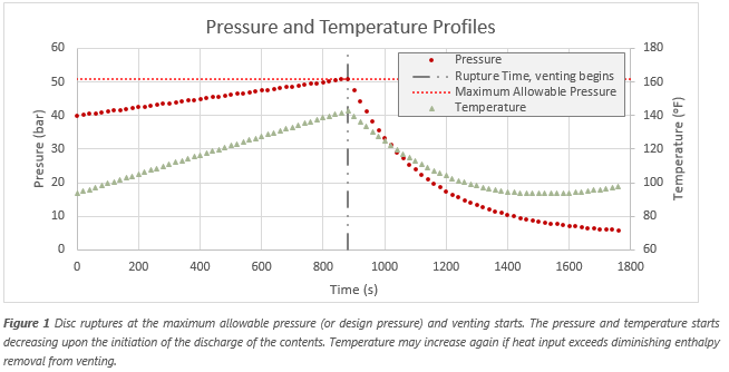
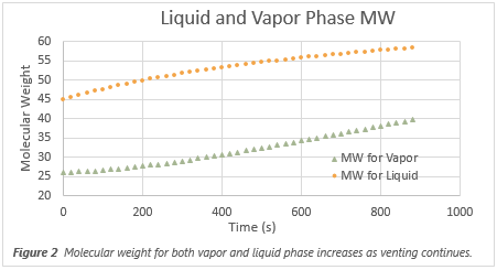
Assuming a liquid is present that does not reach supercritical conditions, this heat input produces a vapor initially comprised of low-boiling components. The
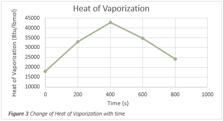
vapor composition changes as the heat input continues, as shown in Figure 2. Although the heat of vaporization increases as the liquid becomes richer in heavy
components, eventually the effects of lower pressures dominates and the heat of vaporization is reduced. The rate at which vapor is generated changes over time
due to the mentioned effects. It is, therefore, important to introduce a time-dependent model for multicomponent mixtures that have a wide boiling-point range
to help calculate the peak relieving rate. Cases should be examined to size an appropriately sized relief system to maintain the pressure in the vessel below
the maximum allowed as these vapors are forming and expanding at higher temperatures.
Effects on Non-Wetted Areas of Vessel
The pressure effects from vaporizing liquids and expanding vapors are not the only concern in situations of uncontrolled heat input to a system. Un-wetted
areas are those that contain a gas, vapor, or super-critical fluid at relieving conditions. The assumption is also made that any vessel internally insulated,
regardless of the contained fluid type, is considered un-wetted as well. Often a two-phase system will become gaseous or super-critical at relieving conditions,
and the sensible heat effects dominate any energy transference. While a vessel with an un-wetted internal wall has a low heat flow in that area as a result of
the high heat transfer resistance of the contained fluid or internal insulating material, the heat input from an open fire to the bare outside surface can be
sufficient to heat the vessel wall enough to rupture.
Figure 4 illustrates the rise in temperature that occurs in time in the un-wetted plate of various thickness exposed to open fire. For example, un-wetted
steel plate 1-inch thick takes about 12 min to reach 1100 °F and 17 min to reach 1300 °F when the plate is exposed an open fire.
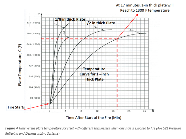
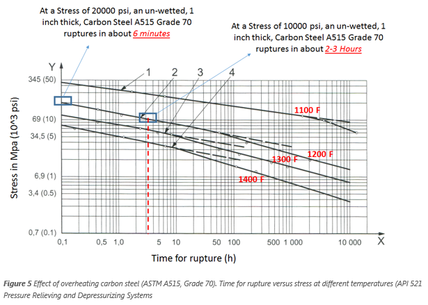
Figure 5 shows the effect of overheating ASTM A515 Grade 70 carbon steel. For a given amount of stress (horizontal line passing through a constant stress value),
time to rupture decreases with increasing temperature. Following line 2 on the figure, we can see that at a stress of 138MPa (20,000psi), an un-wetted steel vessel
ruptures in about 0.1 h (6 min) at 1,200°F. Hence, at this temperature, the rupture is imminent. The stress can be related to the internal pressure of the vessel
using ASME BPV code as;

, where S is the stress in psi, D is the inner diameter of a cylindrical vessel in inches, t is the wall thickness of the vessel, and P is the internal pressure of
the vessel.
For example, an internal pressure of 800 psia can produce 20,000 psi stress in a 50 in. diameter cylindrical vessel that has a 1-inch thick A515 70 carbon steel wall
at 1,200 oF. If a pool fire exposes the un-wetted wall of a large (1-in wall thickness) vessel fabricated from ASTM A515 Grade 70 carbon steel, it will take about 15
min to heat the vessel walls to around 1,200 °F as shown in Figure 4. If the vessel is depressurized to 50% of the initial pressure within the 15 minutes of heat-up time
(from 800 psia to 400 psia), then the stress would also reduce 50% from 20,000 psi to 10,000 psi. Therefore, time to rupture at 1,200 °F would increase to about 2-3 h as seen in Figure
5 (At 10,000 psi stress the rupture time is 2-3 hours).
The relief capacity for a vapor depressurizing service should be enough to permit reduction of the vessel stress to a point where rupture is not of immediate concern. For fire-emergency
cases, this generally involves reducing the equipment pressure from initial conditions to a level equivalent to 50% of the vessel design pressure within approximately 15 minutes. This criterion
is based on the vessel-wall temperature versus stress to rupture, and applies generally to carbon steel vessels with a wall thickness of approximately 1 inch or more. Vessels with thin walls generally
require a faster depressurization rate. Hence, the required depressurizing rate depends on the metallurgy of the vessel, the thickness and initial temperature of the vessel wall, and the rate of heat input.
The ProMax® Depressurization Tool is available to help you evaluate your system in many of these different scenarios. Look for another article soon for more details on how to use this tool in ProMax.
REFERENCES
Significant thanks to Dr. Ugur Guner for his contributions to this discussion.
American Petroleum Institute (2007). “Pressure Relieving and Depressurizing Systems” API 521, 5th Edition.
Fisher, H.G. (1995). Protection of Storage Tanks from Two-Phase Flow Due to Fire Exposure, Process Safety Progress, Vol.14, No.23
Huff, J.E (1982). Emergency Venting Requirements, Plant/Operations Progress, Vol.1, No.4
Leung, J.C. (1986). Simplified Vent Sizing Equations for Emergency Relief Requirements in Reactors and Storage Vessels, AICHE Journal, Vol.32, No.10
Leung, J.C. (1987). Overpressure During Emergency Relief Venting in Bubbly and Churn Turbulent Flow, AICHE Journal, Vol.33, No.6
Salater, P., Overaa, S.J., and Kjensjord, E (2002) Size Depressurization and Relief Devices for Pressurized Segments Exposed to Fire, CEP